Boat Bonding System Diagram
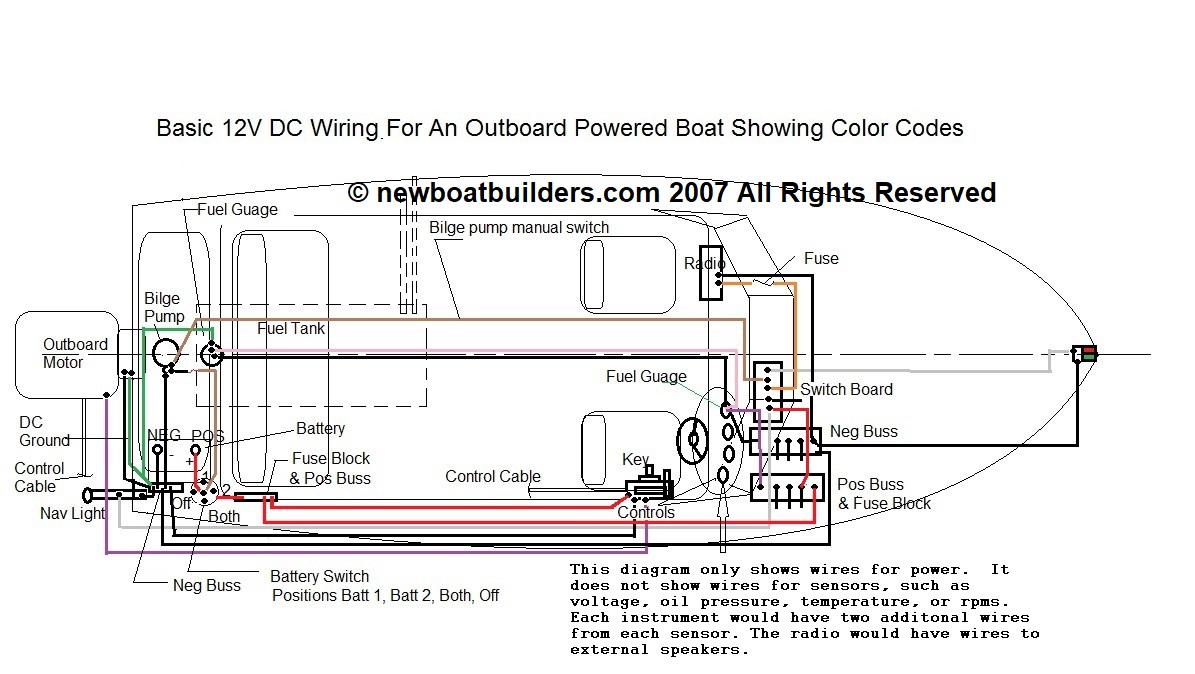
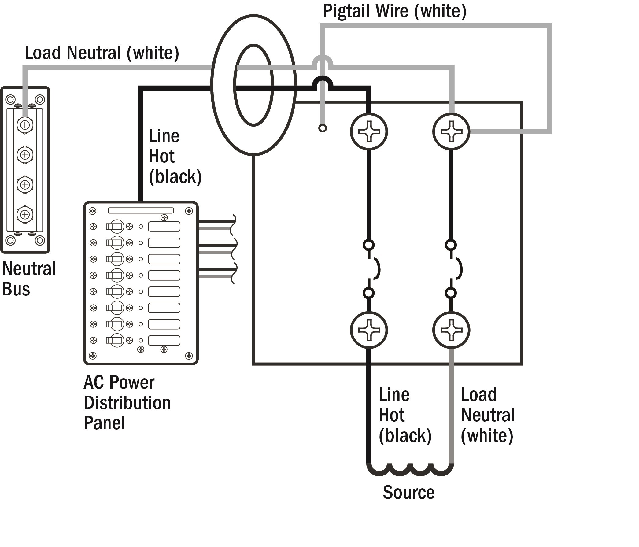
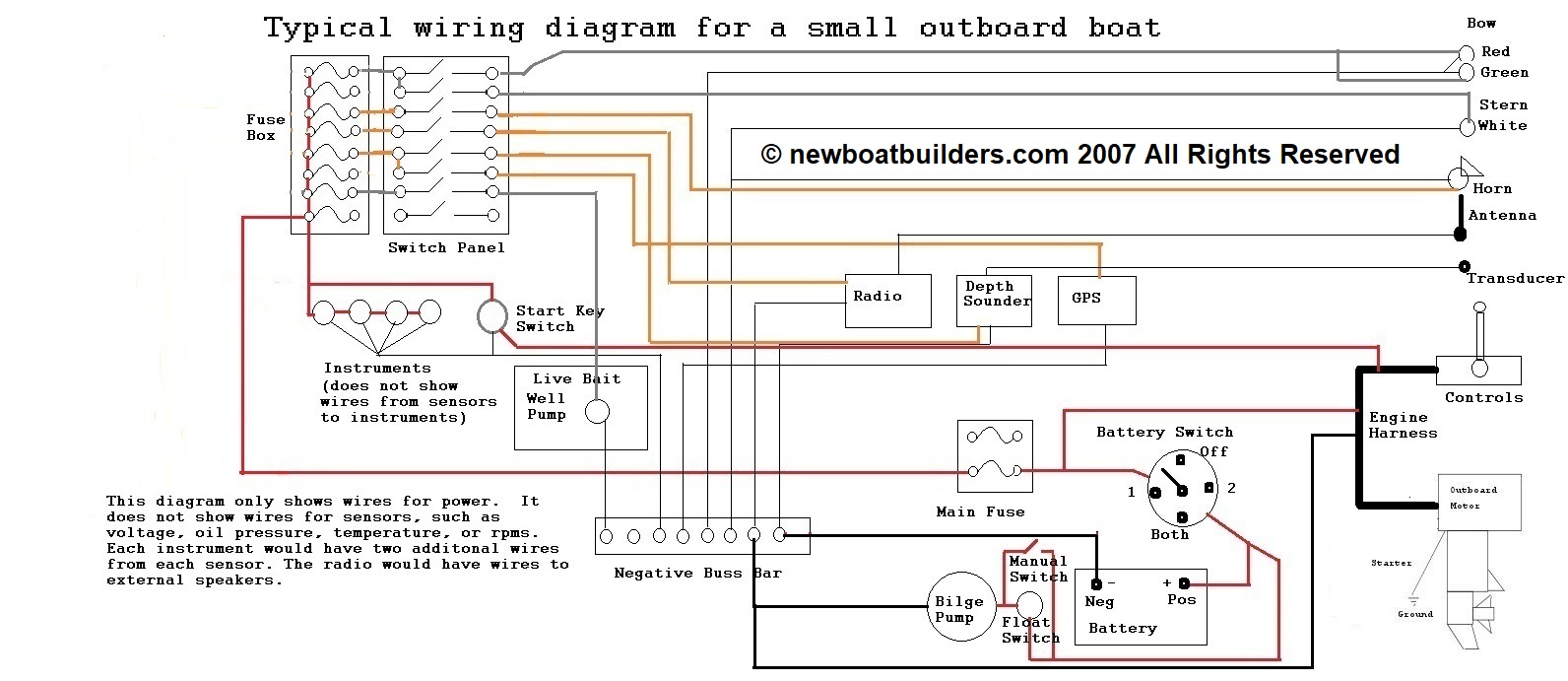
Boat bonding system diagram. Variety of boat bonding wiring diagram. By Dana Gaynullina On June 21 2021 In Wiring Diagram 147 views. A wiring diagram is a streamlined standard photographic representation of an electrical circuit.
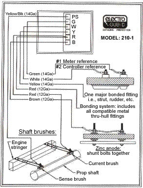
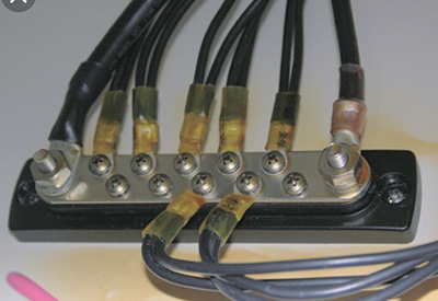
In typical dockside conversation the bonding system is often thought of as limited to the wiring shown on the right-had side of Figure 1. A text book example of how not to make a bonding system connection. The attachment studs should be bronze not brass which is alloyed with copper and zinc the nuts and flat washers also in bronze and the connecting wire ends should have tinned terminal lugs.
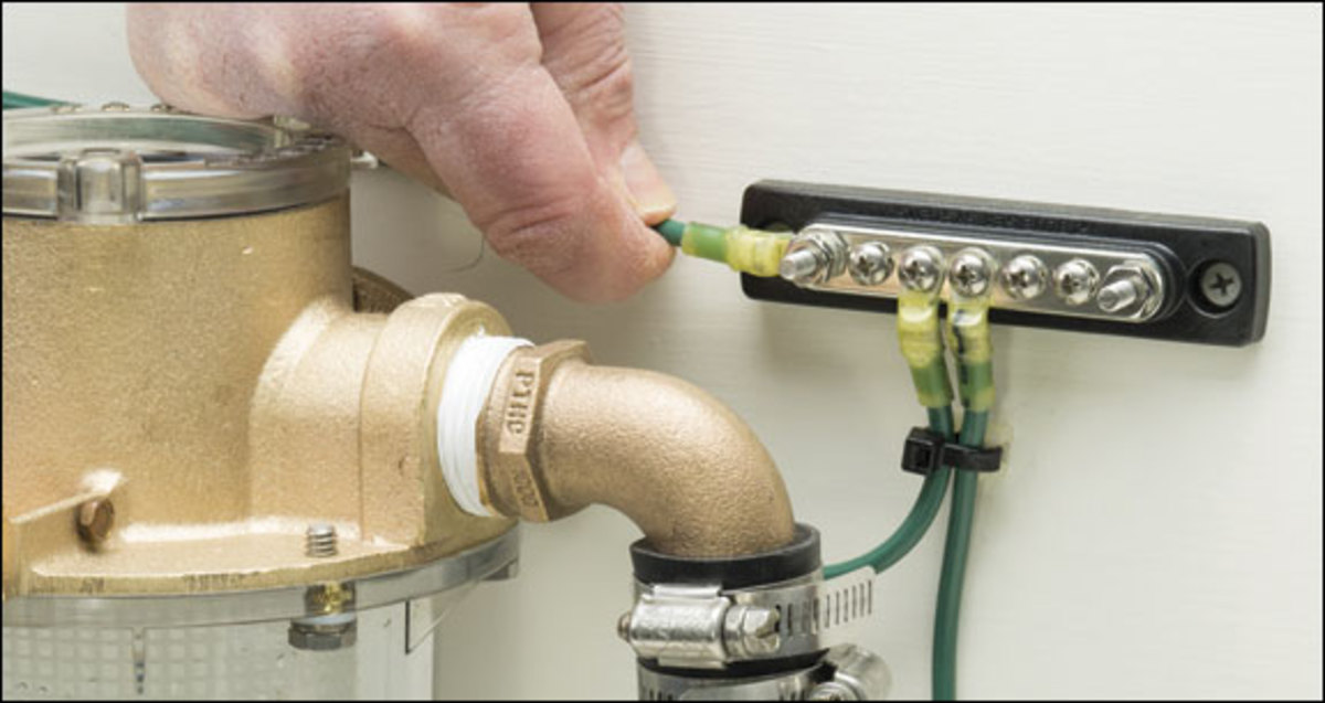
PPM modes is that you dont need to keep track of all of your cables typically one per channel. Designing a marine exhaust system for a boat is something that apparently takes the back seat during the planning stages when doing a repower. For those of you who have no idea what the bonding system on your boat looks like the photo below shows a green wire connected to a sea strainer.
Ensure your bonding system is doing its job. In all cases the bonding strap or wire is not to serve as a current carrying negative electrical wire. The primary strip should be copper at least 26 gauge in thickness and 1 in width.
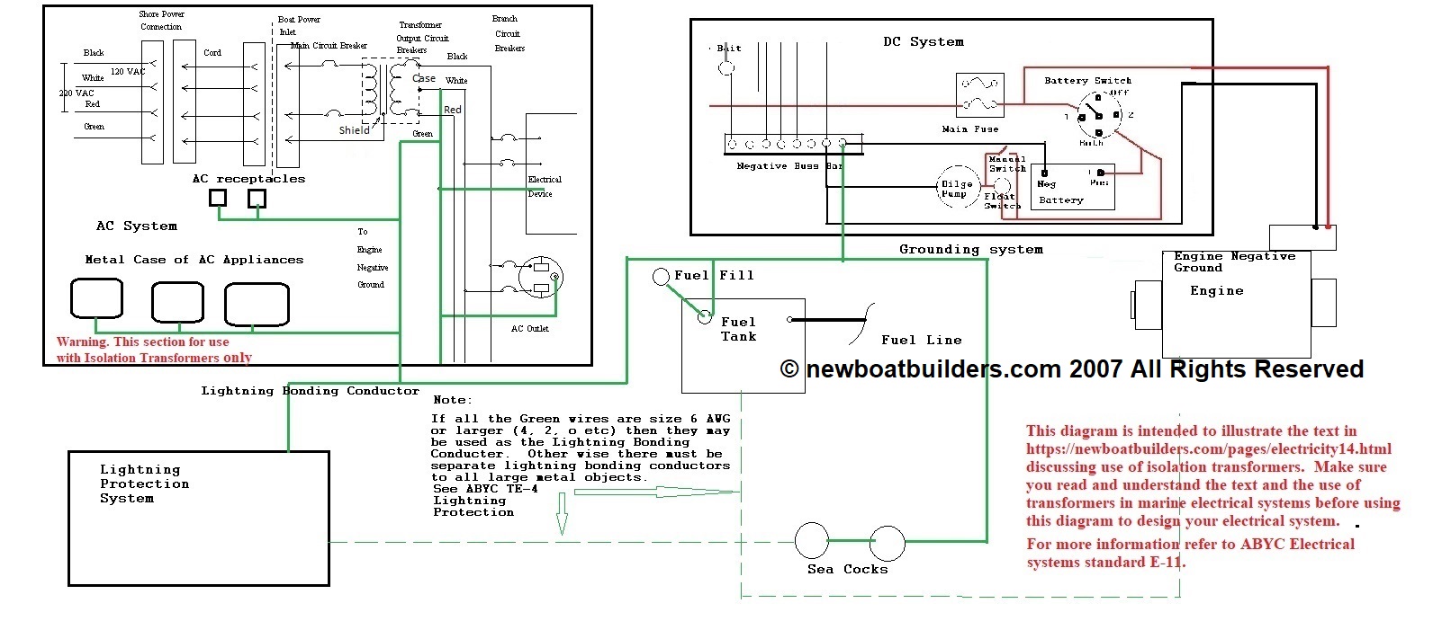
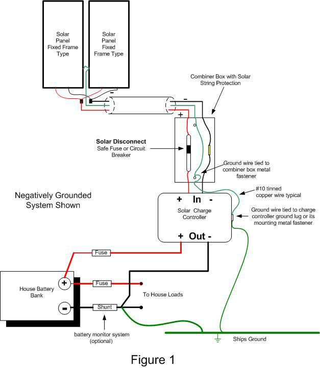
It shows the components of the circuit as streamlined forms and the power and also signal links between the gadgets. All of the conductors shown in green in Figure 1 are part of the boats bonding system or bonding network That entire network of conductors works together. That wire is there to attach the strainer to the boats bonding system.
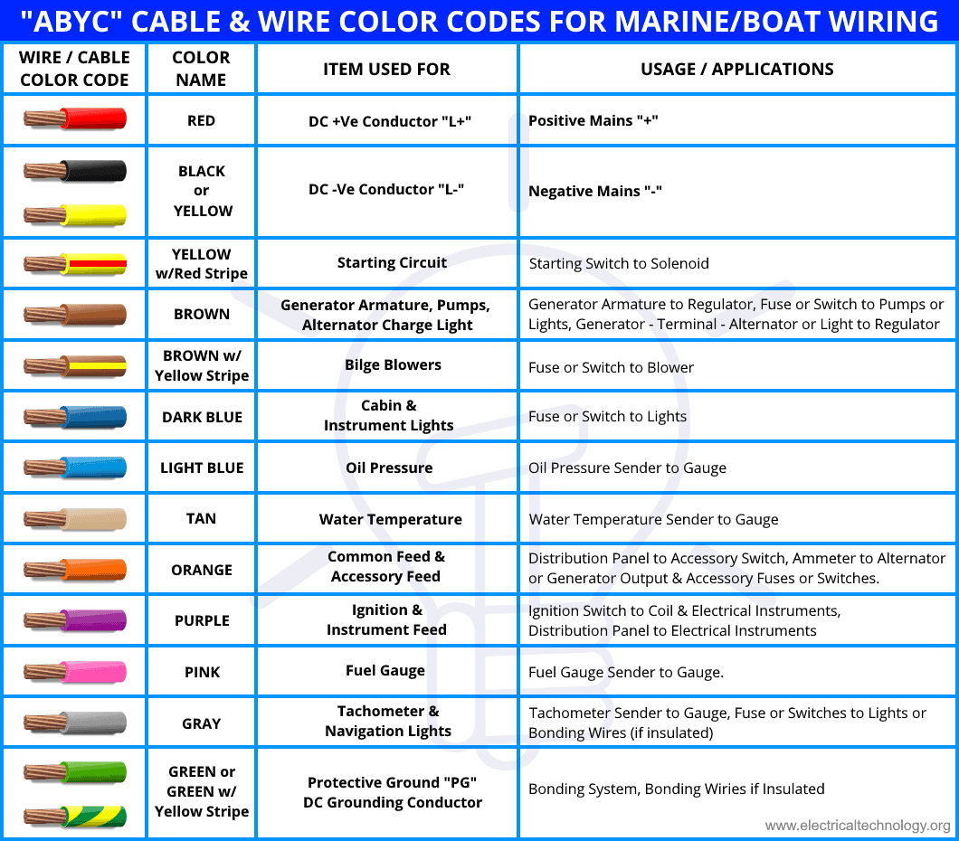
These systems are called bonding systems and consist of green wires or green wires with yellow stripes connecting all the metal components in contact with water. It reveals the elements of the circuit as simplified forms and also the power and also signal links in between the gadgets. Moreover all electrical equipment and large metal objects should be grounded to.
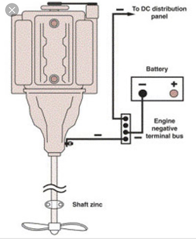
If you are one of. To the engine negative terminal or the DC main negative bus as illustrated in the bottom part of the following diagram.
Continuity of the grounding path shall not rely on water meters or fi ltering devices or similar equipment according to 25053D1 of the Code.
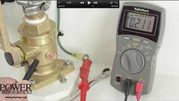
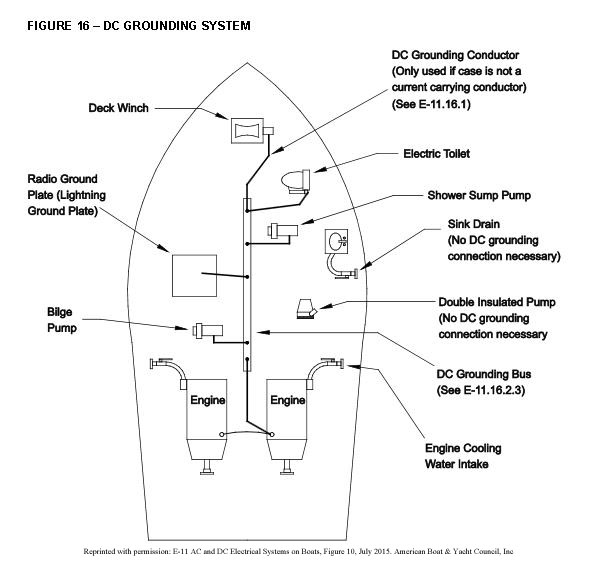
Proper marine circuit protection is a critical part of your boats electrical system. Grounding and bonding are probably the most misunderstood terms when it comes to boat wiring. Proper marine circuit protection is a critical part of your boats electrical system. A wiring diagram is a simplified standard photographic representation of an electric circuit. A separate system electrically connecting all metal fittings on the boat that are in contact with the water including the sacrificial anodes and connecting them to the earth ground so they are all at the same voltage potential zero. The bonding system is used to interconnect among other things underwater metals such as through-hull fittingsseacocks rudders and stuffing boxes including the rudders. One of them has to do with bonding and grounding the other anode consumption and the third with transducers and fairing blocks. Bonding jumpers shall be connected around meters fi ltering devices and similar equipment. Collection of boat bonding wiring diagram.
Learn how you can enable PPM output mode on the FlySky FS-i6 transmitter and use it with the FlySky FS-iA6B receiver. In typical dockside conversation the bonding system is often thought of as limited to the wiring shown on the right-had side of Figure 1. It reveals the elements of the circuit as simplified forms and also the power and also signal links in between the gadgets. In all cases the bonding strap or wire is not to serve as a current carrying negative electrical wire. That wire is there to attach the strainer to the boats bonding system. Learn how you can enable PPM output mode on the FlySky FS-i6 transmitter and use it with the FlySky FS-iA6B receiver. For older boats they can be completely out-of-date or non-existent.

















Post a Comment for "Boat Bonding System Diagram"